Table of Contents
Maximizing Print Quality: Advanced Calibration Techniques for FDM Printers
High-speed FDM printing can look impressive at first. Spec sheets often promise huge gains. In real use, though, speed by itself rarely delivers good results. Many engineers find that a fast printer with poor calibration ends up wasting time and money. Parts might look fine at the start, but holes often print slightly out of size, and layer bonding can be weaker than expected. These problems usually show up later, when fixtures fail early and the reason isn’t obvious right away.
That’s why calibration matters more today than it did a few years ago. As FDM systems move into real production work, print quality needs to stay consistent day after day, not just on a lucky run. Calibration isn’t treated as a quick setup task anymore. It’s now part of process control, sitting next to material profiles and regular machine checks, which is where it makes sense.
This guide walks through advanced calibration techniques for FDM printers, focusing on what actually improves print quality as speeds increase, instead of theory for its own sake. You’ll see how extrusion, motion, thermal control, and firmware tuning work together in real machines, along with common mistakes and how industrial teams usually avoid them.
The article is written for engineers and serious users in Australia, especially those running RatRig V-Core systems or Klipper-based machines. It begins by examining how calibration has become a competitive advantage in modern manufacturing, and why it’s often the real reason some teams get better results.
Why Calibration Is Now a Production Requirement
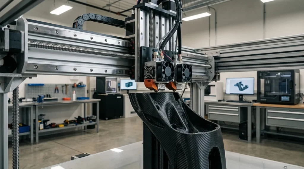
FDM has changed. It’s no longer just about desk prototypes. Today, industrial FDM printers are used for jigs, fixtures, tooling, and real end‑use parts. You can see this in market data and daily team use.
| Metric | Value | Year |
|---|---|---|
| Global FDM market size | USD 2.10 billion | 2024 |
| Projected FDM market size | USD 15.09 billion | 2034 |
| Industrial printer revenue share | ~76% | 2024 |
| Businesses using FDM | ~71% | 2024 |
Most revenue now comes from industrial‑grade systems, as the table shows. These users care about repeatability. A part printed today needs to match one printed next month on the same machine, with the same settings and no surprises. That consistency comes from proper 3D printer calibration.
Speed makes this more important. Small errors turn into big problems fast. A 2% extrusion error may slip by at 60 mm/s, but at 300 mm/s it often causes weak walls or failed corners. Engineers may blame materials or slicer settings, but calibration is usually the real issue.
That’s why industrial teams treat calibration like machine qualification. Flow rate, motion limits, and first‑layer control are tracked and reviewed in normal operations. It’s not something they skip.
Extrusion Calibration: The Foundation of Print Quality
For most printers, extrusion is usually the first thing to get right, because almost everything depends on how much plastic comes out of the nozzle at any moment. If too much material is pushed through, walls can start to bulge and tolerances slowly drift, which is often easy to spot after a few layers. Too little material causes the opposite issue: parts lose strength, and small gaps appear where they shouldn’t. In practice, the connection is very direct, and there’s usually not much guesswork involved.
This idea is explained clearly by Jonathan Smith, a long-time contributor on the Prusa3D forum. He keeps things short and hands-on, which helps when the goal is fixing real prints instead of getting lost in theory.
Extrusion multiplier… IMO, this is the single most important setting that should be done before the rest as it impacts them all.
Once basic E-steps are finished, more advanced extrusion calibration can start. At this point, engineers often care less about the numbers on screen and more about how material behaves during an actual print. A common method is single-wall testing: printing one perimeter with no infill, then measuring the wall with calipers to see what really printed.
The goal is simple. Wall thickness should match the slicer setting. In industrial settings, teams often aim for less than 0.01 mm of variation, since that level of control usually leads to parts that fit well and last.
High-speed printers make this matter even more. PLA usually flows easily, even at higher speeds. Nylon and fiber-filled materials act differently, resisting flow and reacting strongly to temperature changes. That’s why many setups use per-material flow profiles, each with its own multiplier and tested temperature range. Close enough, most of the time.
First Layer Control and Z-Offset Drift
The first layer often sets the tone for how the whole print behaves. In production, when that layer fails, it usually costs more than just filament. Time is lost, machines sit idle, and operators get pulled away from other tasks, which can slow everything else down. Even automated setups aren’t as protected as many people think. When the Z-offset starts to drift, problems often appear fast, sometimes only minutes into a job.
Jonathan Smith points to a detail many users often miss. It looks small at first. But in real use, it can decide whether a print ever gets past layer one, and most operators have seen this kind of quiet failure before.
The single commonest calibration is first layer Z offset, it will drift over time as your nozzle wears.
Nozzle wear plays a bigger part than it usually gets credit for, especially with abrasive materials. Carbon fibre filaments, for example, can wear down a nozzle faster than expected. At higher speeds, even a 0.1 mm change can be enough to break first-layer adhesion.
Industrial teams usually stay ahead of this with routine checks. Z-offset is checked on a schedule, not only after problems show up. Probes and load cells help, but manual checks still matter. These habits exist for a reason.
Bed mesh systems also need realistic expectations. A mesh can help with surface variation, but it won’t fix a bad Z-offset. Experienced users treat these as separate steps: true zero first, mesh second, if needed.
On IDEX machines, this becomes even more important. Both toolheads need matching Z heights. When they don’t, dual-material prints can fail in subtle, frustrating ways, sometimes after looking fine at the start.
Motion Calibration: Input Shaping and Pressure Advance
Once extrusion and Z control are stable, motion tuning is usually where print speeds really start to rise, and where the process begins to feel rewarding. Firmware like Klipper helps a lot here because it gives detailed control after the basics are sorted out. When a machine is already behaving consistently, two tools usually make the biggest difference: input shaping and pressure advance.
Input shaping focuses on vibration. Fast direction changes make the frame flex slightly, and that movement often shows up as ringing or ripples on vertical walls. By measuring how a specific printer vibrates, input shaping counters those movements in software. The result is smoother surfaces, even when acceleration is pushed higher than before.
Pressure advance focuses on plastic flow. Speed changes create pressure delays inside the nozzle, which can cause corners to bulge or lines to vary in thickness. Pressure advance adjusts extrusion in real time so flow matches motion, especially around sharp turns.
Studies and industrial trials consistently show that these tools allow large speed gains without losing accuracy. This usually isn’t hype. Many users see prints finish 40, 70% faster while quality stays the same or even improves, which comes from motion control based on real physics.
One thing that often trips people up is tuning motion too early. These settings work best after extrusion is fully dialed in. Otherwise, problems overlap, and troubleshooting quickly becomes confusing and frustrating.
Thermal Stability and Continuous Printing
Thermal control usually doesn’t get much attention until a print fails halfway through, which is frustrating in a very real way. In industrial settings, printers often run for hours or even days at a time. Heat slowly builds up, behavior starts to change, and a setup that looked fine at minute ten can begin to fall apart by hour four. Most of the time, you only realize something went wrong after the job is already ruined.
One of the more effective ways teams handle this is advanced calibration, most often through PID tuning on the heaters. The goal is simple: keep the nozzle and bed temperatures steady, even during fast moves or repeated cooling, which is where problems often start. Modern controllers like Klipper help with this, but they still require testing and adjustment. There usually aren’t any real shortcuts.
Enclosures add another factor to consider. They help layer bonding for engineering materials and hold in heat, but over time motors and electronics expand slightly. That expansion can lead to small but noticeable dimensional changes.
Because of this, experienced teams often run calibration prints at full operating temperature. Fully warming up the machine first usually gives more reliable measurements than starting cold.
Engineers at Ultimaker often point out that steady extrusion and thermal stability matter most in day-to-day use. A machine that stays consistent tends to make better parts, even if its listed resolution isn’t the highest.
Building a Repeatable Calibration Workflow
Turning calibration into a system is often when things start to make sense. Industrial users don’t rely on memory or guesswork, and that habit usually pays off. Settings are written down, results are tracked, and small problems are less likely to get missed. It can feel boring at times, but it often cuts day‑to‑day stress more than you’d expect.
Instead of leading with rules, the real value is in the outcome. A solid workflow makes adding another printer much easier. You’re not starting from scratch; you’re repeating what already works, which helps scaling feel manageable. This matters in education and production labs across Australia, where running multiple machines is common.
A setup like this usually includes:
- Regular checks for extrusion and Z‑offset, often weekly or after changes
- Per‑material profiles saved in firmware or the slicer, based on real use
- Motion limits set per printer, rather than loosely shared
- The same test parts reused over time as quality benchmarks
Local support helps too. Suppliers who understand calibration at this level often save time, especially when issues keep coming back. Hardware also matters. Platforms like RatRig V‑Core systems and IDEX printers respond well to careful setup, delivering speed and precision that can compete with far more expensive machines when tuned properly.
Putting Calibration to Work in Real Production
Advanced calibration usually isn’t about chasing perfection. Most of the time, it’s about staying in control. When material flow and overall machine behaviour are handled well, print quality becomes predictable by design. That kind of reliability is what turns FDM into a practical manufacturing tool when parts are running day after day.
The main takeaway from this guide is pretty simple. Following a clear calibration order cuts down on guesswork. Measuring carefully almost always works better than relying on feel, and shortcuts rarely pay off. When a printer is treated like any other workshop machine that needs repeatable results, it tends to deliver fewer surprises than people expect.
So where should you start? Extrusion stability comes first, then setting Z-offset so the first layer behaves properly on the build plate. Motion settings matter too, especially at higher speeds. Stable temperatures help, and writing down every change often saves time later, notes usually beat memory.
For Australian engineers and educators, this approach often helps close the gap between prototyping and production, with strong, accurate parts appearing on demand, job after job.
